Average response time: under 24 hours
A laser-screed slab places and consolidates concrete with a vibrating beam guided by a laser level; it is flatter and more uniform than a hand-trowelled pour, but polishing exposes the screed behavior underneath: early bleeding, finishing laps, joint timing and travel lines. This article covers contractor-side acceptance: tolerance measurement, the curing window, slab moisture, saw-cut schedule, panel zoning and equipment routing. Figures are planning targets; final limits follow the specification and project drawings.
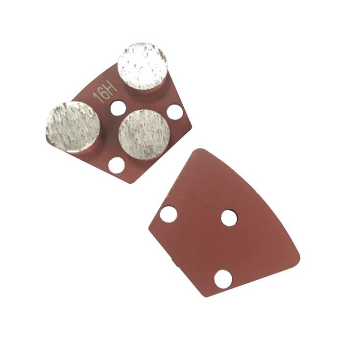
A laser-screed slab has tight level control but can carry its own defects: low spots at beam ends, over-vibrated paste near edges, trowel laps and boot marks. Polishing at 16/20/30/40 metal grit opens the surface and makes these visible under 300-500 lux raking light; resin phases at 100/200/400/800/1500/3000 even the sheen but cannot fill a structural low spot. Review pour records and finish passes before pricing the polish scope.
Define whether the spec controls flatness, deviation from a plane, or level, elevation from a datum, and state the measurement method. Common practice checks PTV over a 2 m straightedge at 3-5 points per 100 m2; polished warehouse slabs commonly accept 2-3 mm PTV over 2 m, showroom or display areas 1-2 mm. Record each reading with its grid location so rework targets a zone, not the whole slab.
| Parameter | Target | Method | Acceptance action |
|---|---|---|---|
| Flatness PTV, 2 m straightedge | 2-3 mm general; 1-2 mm display | Straightedge plus feeler at grid points | Grind high spots; do not fill low spots |
| Level deviation from datum | ±3-5 mm per bay | Laser level or total station | Record bay readings; low area belongs to slab scope |
| Joint alignment | Within 5-10 mm adjacent panels | Straightedge along joint | Mark offset for edge grind |
| Surface profile | CSP 3-4 standard; 1-2 exposure; 5-7 near-mirror | Profile comparator at sample point | Match profile to spec finish class |
| Gloss evenness | Adjacent areas within 5 gloss units | 60° meter on grid | Over 15 units difference needs rework |
Fresh laser-screed concrete bleeds water to the surface as the beam and vibration settle the mix. Polishing cannot start until bleed water has evaporated, the surface has reached final set, and curing has progressed enough that paste does not pull out under the shoes. The typical waiting window is 7-14 days after pour for the first metal grind on normal slabs; high-strength or air-entrained mixes may need longer. Test by dragging a shoe or nail: no paste transfer means ready for the first pass.
Moisture controls when densifier and resin phases may follow. Take RH tests at 40% of slab thickness in drilled holes, sealed 24 h before reading; ambient RH should stay below 75-80% and surface temperature 10-30 C during chemical application. If readings run high, hold densifier and resin phases, resume drying, and retest; grinding over a damp slab traps moisture under later coats and shows as haze or blotchy gloss.
Joints must be cut before restrained shrinkage cracks form. For most slabs, saw cuts start 6-24 h after final trowel, when the edge does not spall during cutting; delay past the window and random cracks appear ahead of the joint saw. Cut depth is 1/4 to 1/3 of slab thickness, joint spacing 6-12 m depending on slab depth and reinforcement. Plan cuts around panel zones so grinder and edge tools run straight segments without crossing a fresh joint.
Divide the slab into polish panels aligned with joints, columns and equipment access. Sequence phases panel by panel: metal leveling first across the whole zone, then resin refinement within each panel; keep one machine per panel to avoid crossing wet densifier lines. Mark travel lines on the layout: machine infeed, slurry disposal, tooling change points and the exit route for waste. Keep edge bands 100-200 mm along walls and columns for hand tools after the main machine passes.
Follow the standard sequence: metal 16/20, 30/40 to level high spots and open paste, then resin 100/200, 400, 800, 1500, 3000 to the target sheen. Correct screed defects in the phase they appear: high spots and beam-end ridges come out in metal grit; trowel laps and swirls need an extra resin pass; a low spot cannot be ground out and must be recorded for the slab contractor. Match edge tool grits to the field sequence and blend a 150-200 mm overlap.
Walk the finished slab under 300-500 lux raking light with the owner rep: check gloss evenness, edge bands, joint condition, scratches and clouding. Slip resistance: dry PTV at least 36, wet PTV 10-20 points lower, DCOF at least 0.42; wet zones grade R10-R12 as specified. Common disputes are low spots blamed on polishing, joint spalling from early machine traffic, and gloss mismatch between panels; resolve each against the pre-polish baseline photos and the measured tolerance record.
Hand over the tolerance grid, RH readings, grit sequence run, defect list and any deferred items. If the slab falls outside the agreed flatness limits, state whether correction belongs to grinding, topping or the slab pour in the handover note; this keeps polish scope from absorbing structural slab defects.
Written and reviewed by JOY TECH - an SGS & BV audited, CE/RoHS certified diamond tools manufacturer founded in 2004, exporting to 50+ countries.
Our factory and quality management system are audited by SGS and Bureau Veritas. Products meet CE/RoHS requirements and every piece is 100% inspected before packing.
Verified Certificates
